


 Visit the Project VGA Page


Card assembly
Update 2008/01/08: Finished assembly prototypeUpdate 2008/01/07: Work in progress picture added
Posted on 2008/01/05 - 13:03
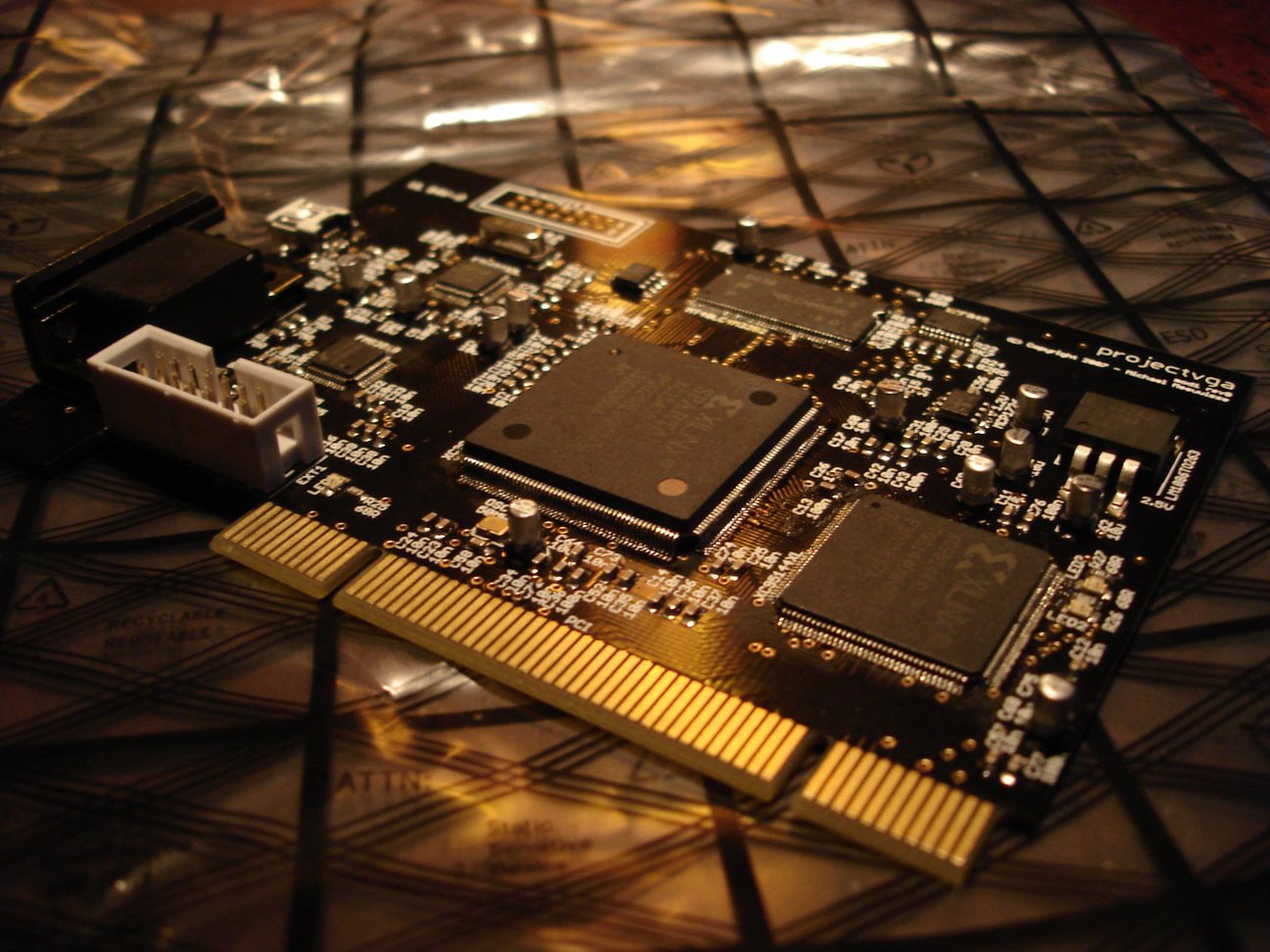
The circuit boards arrived yesterday! Four days early! They all appear to be in perfect order, except for two little cosmetic issues on one of them. Since I only have components for two cards anyway and am now the owner of three circuit boards, this one will be used last, if ever, as a prototype. Enough talking, time for pictures!
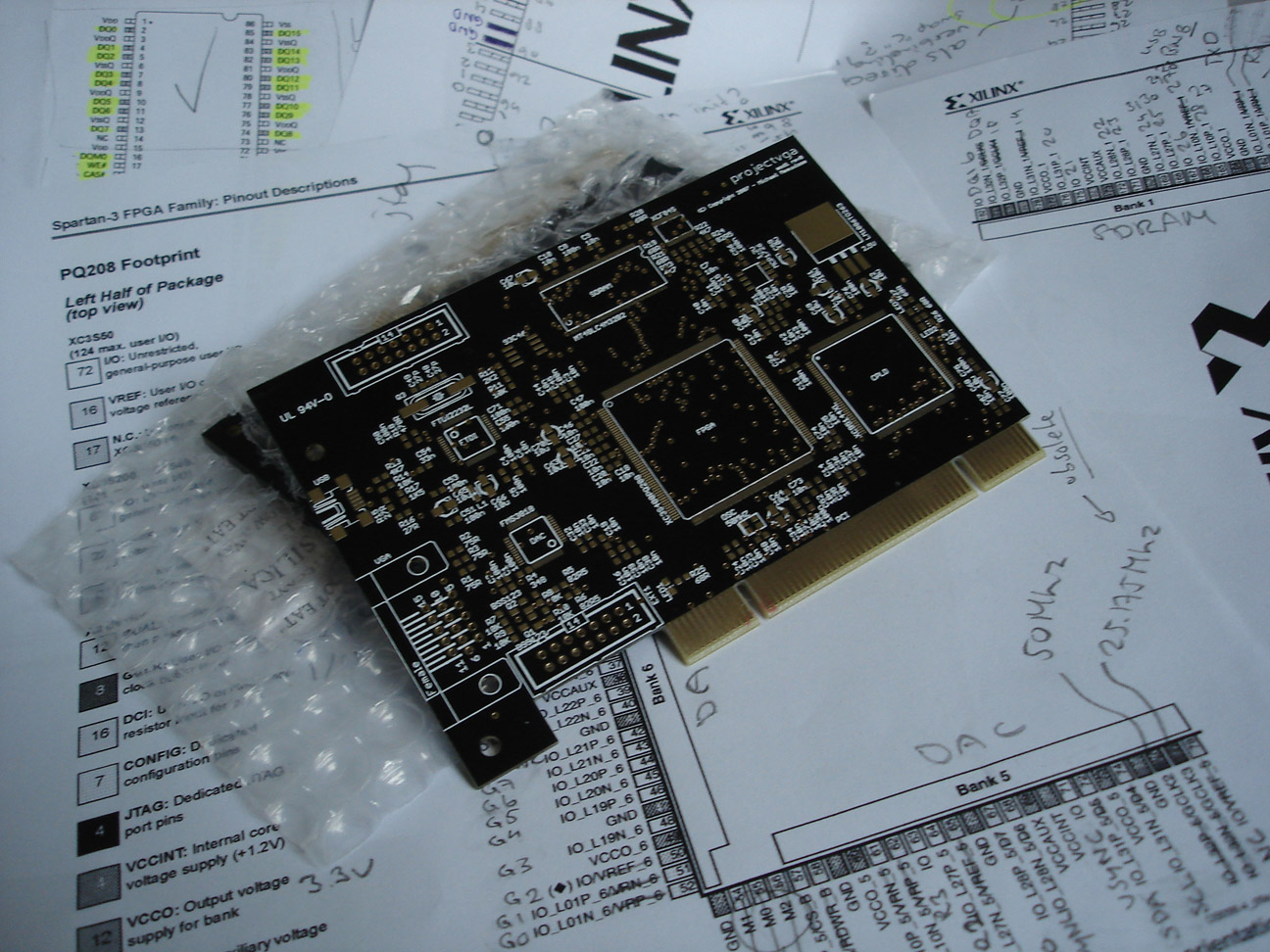
Pictures by Stefan
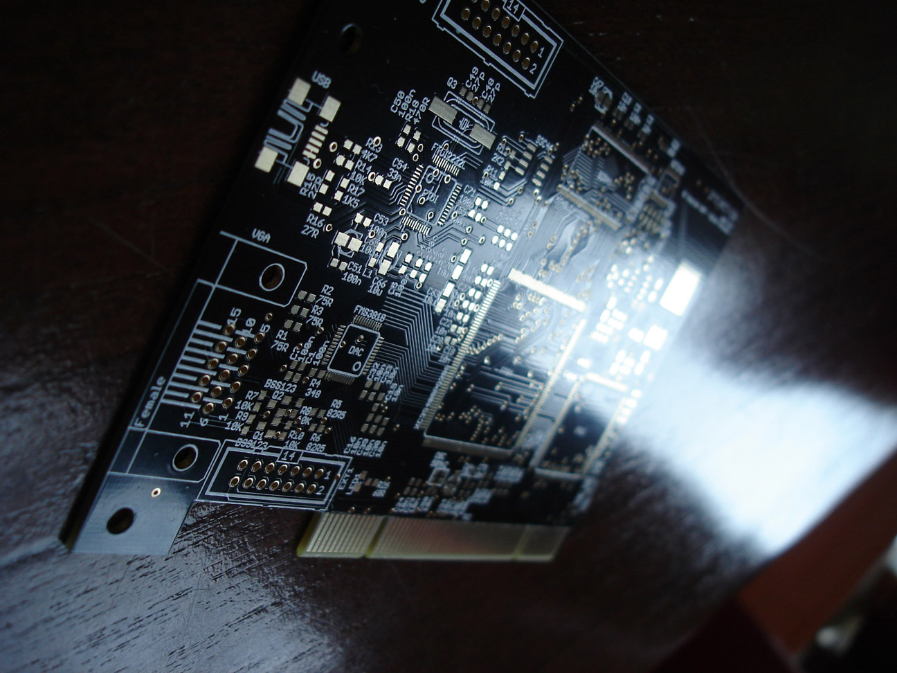
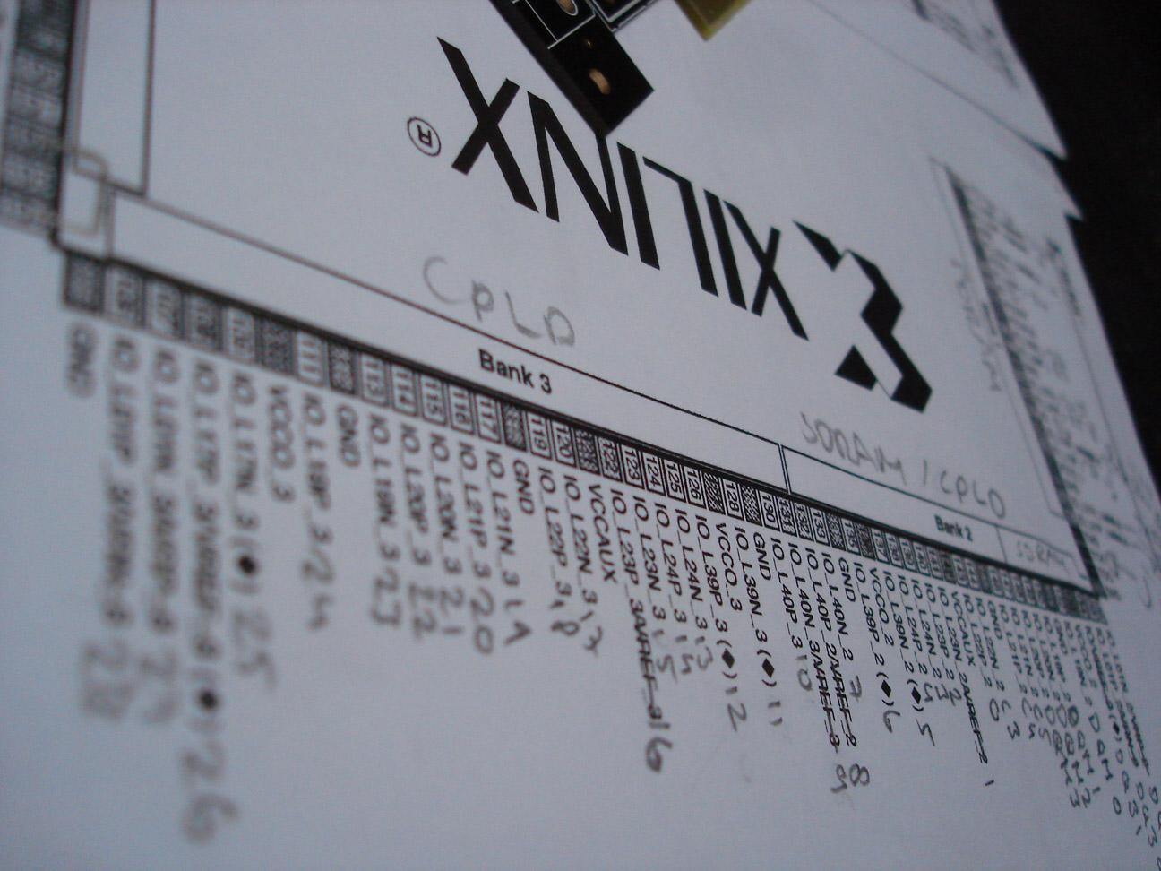
That last picture is just a little bonus to give you an idea of how I planned the FPGA IO, which is used as a background for some of these pictures. The black finish makes it really hard to get the wires showing on a photo so Stefan had to play a bit with the light to give you an idea of how it looks. I'm extremely happy with how they turned out.
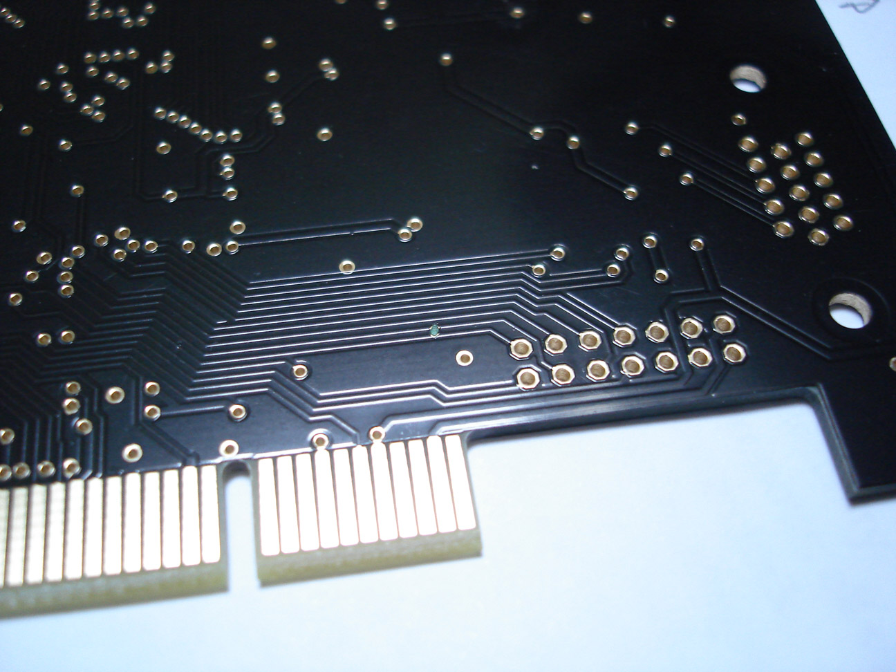
Some details
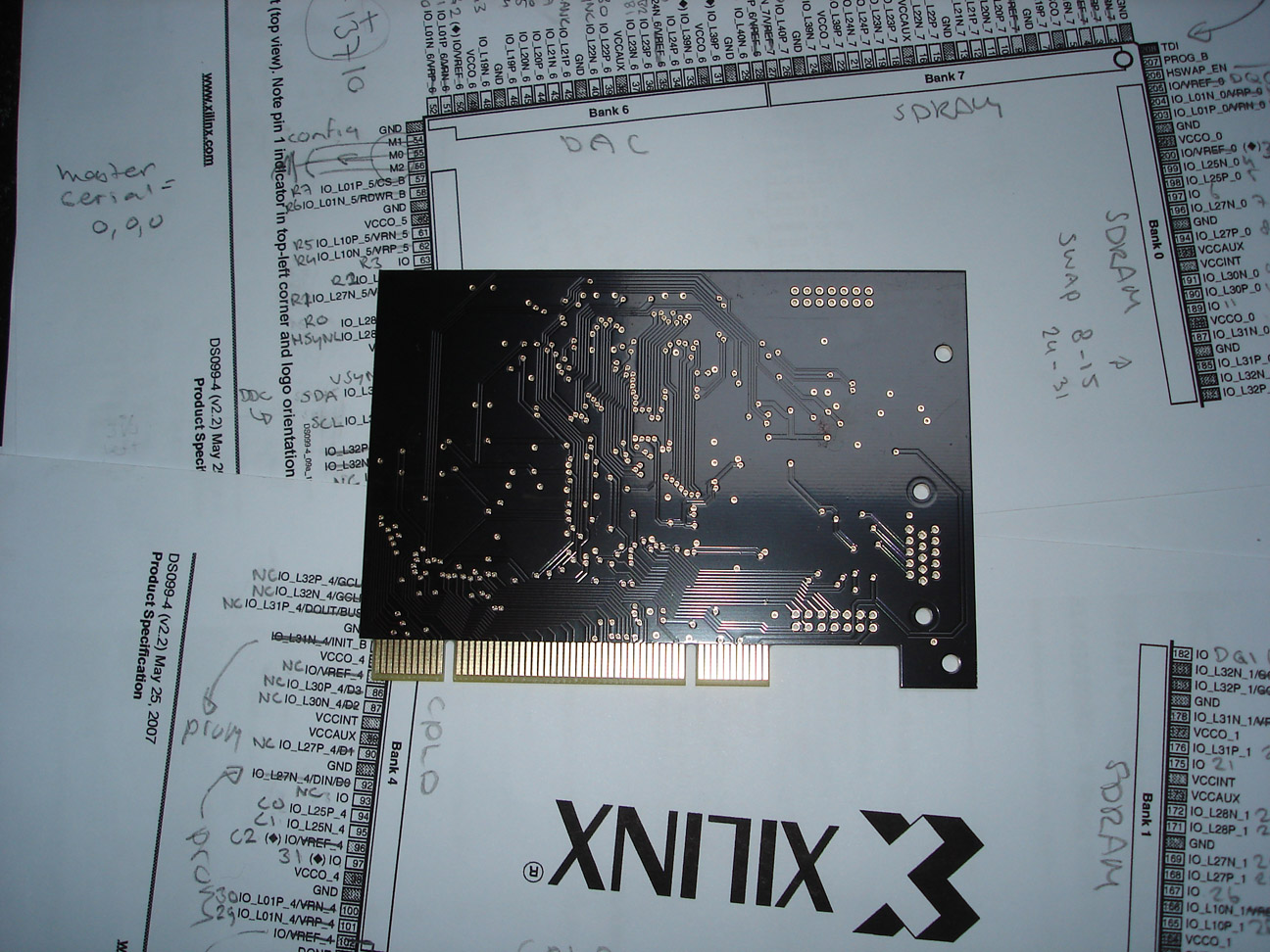
On the left you can see a little green dot on top of the lower two data signals going to the extension connector. I'm not sure what it is, but it's not supposed to be there and it's stuck. You can see that the solder mask didn't attach to the board there, and the wires have gotten a little solder finish. Luckily, there's no shortcut between the two wires and even if it did it's "only" the extension connector that wouldn't work. It does make me paranoid enough however to not use this board. It also has a little spot somewhere else where it looks like the solder mask didn't fully attach to the board either, but it's in the middle of a ground plane so it doesn't matter.
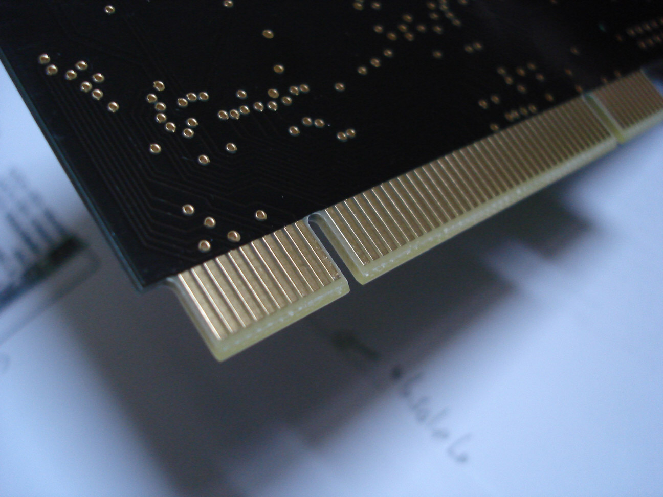
On the right you see the finish of the PCI connector. Although I didn't give PCBcart explicit instructions they figured it was in fact a PCI connector and made the cutouts round (although that might've been because their CNC machine couldn't get a straight cut there) which is perfect, and also trimmed the end of the connector a bit giving it a V shape, so you can really plug it in a connector.
Next monday Reinder and me will be (if all planning goes well) putting the first card together, so more pictures will follow then on this page.
Update 7 Jan:
Didn't finish today, we we're almost there but the lab at university closed for the night, so we had to leave. The
through hole connectors are still not placed, all the pins have to be tested before I'm even considering powering
it up since we were way to enthousiastic with the solder paste and I'm not sure we've fixed everything already and
the PCI bracket isn't finished yet (although that's really an optional thing). For your entertainment, a little
preview:
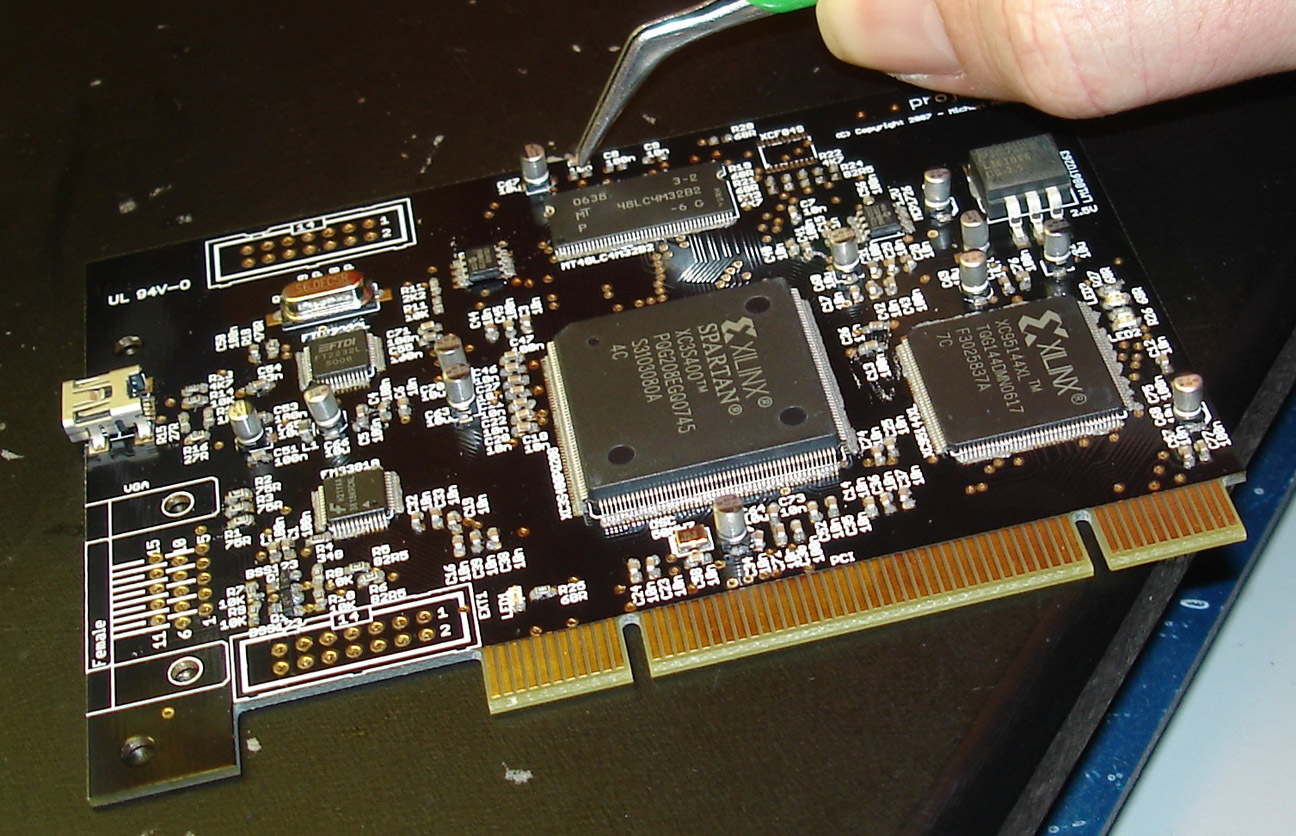
Reinder placing some capacitors
Update 8 Jan:
Well, between all the other stuff I had to do today I managed to get some work done on the prototype. I found a
couple of electrical shortcuts which we got rid of after some fighting with litze. To name a few; LED1, the USB
connector and the clk line of the DAC which where troubling. Hopefully they're all correct now. I find LED3 of
the FPGA suspicious since it wouldn't light up when I measured it for resistance, but that could be because the
meter wasn't providing enough current. Still, if the FPGA isn't able to get it lit either I'll have to replace it
since LED1 and LED2 would light up without a problem. I'll have to thank a couple of the guys from the E-tech lab
here for helping me out with some of the soldering work, it's not really my area of expertise and these guys did
an amazing job in virtually no-time.
But anyway. All the connectors are now placed, all the components are soldered, and I'll be measuring like for the next day or so. I want to make absolutely sure that everything is correct before I power it up, which I haven't done yet. For all I know this card might be "DOA". In the design I already spotted two minor issues; First, the PCI pins TDI and TDO aren't connected. Although this is probably not a problem, it might prevent the system I'm going to plug it in from powering up. And second, there's no "AC connection" for the M66 pin on the PCI connector; I forgot to place a capacitor there. Again not really a big issue but it might make it impossible for the system to detect the prototype as a 66 MHz compatible card. We'll have to see. And now for your entertainment a bunch of pictures. Unfortunately the sun is already gone so I'll update these with better pictures tomorrow but didn't want to keep you waiting.
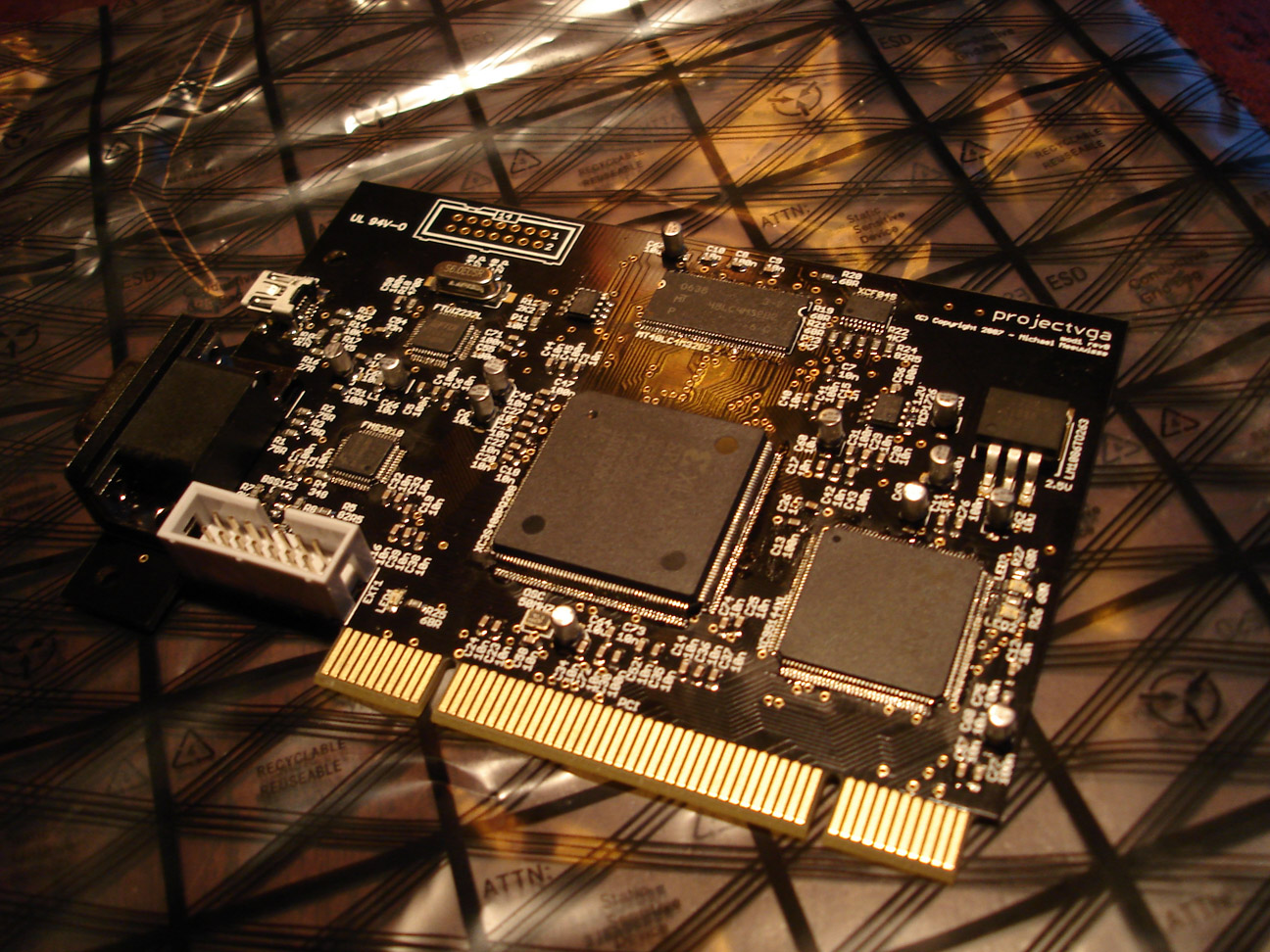


Finished assembly first prototype
On Thursday I'll hopefully be finishing the PCI bracket. In the mean time we'll have to do without. Thanks again to everybody who helped out here and there!
[: wacco :]