


 Visit the Project VGA Page


Module Design
Update 2007/12/28: Added module descriptions, changed talk about bus C.Posted on 2007/11/18 - 22:57
This is very much a work in progress. Feedback will be appreciated, nothing is definitive yet. This article will expand the moment more details are worked out.
Good news everyone! -- Hubert J. Farnsworth
After lenghty consideration I figured, what the hell, and switched to the GNU General Public License 3.0 so that should at least get a lot of those "You're not really Open Source!" smartasses out of the way. So there. I haven't checked everything yet so you might find BY-NC-SA still somewhere. Let me know if you spot it, I'll remove it at once.
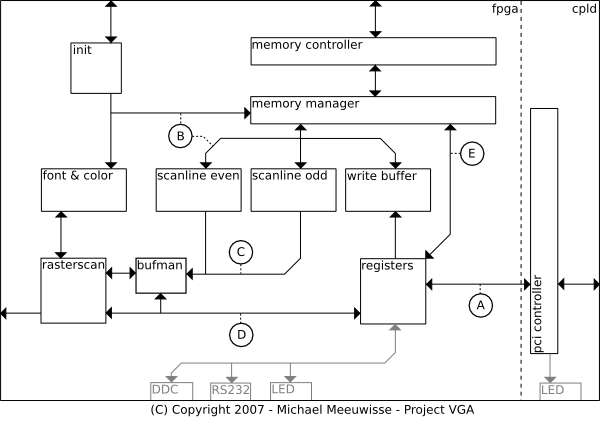
I finally found the time to get accustomed to Inkscape, but only because it got about damn time that I figured out how to use graphics editor. So, if you haven't seen it yet, the talk about communication now has an accompanying Block Diagram to clarify a whole lot of things. This also gave me the possibility to sketch up some doodles I had laying on my desk for a while now, and worked out the module design for the FPGA and CPLD. After about a day work (I didn't say I got fast with inkscape) I ended up with this:
HDL Modules
So, right. I figure nobody really wants to read all of this right from the start, so I'll split it up in individual sections which discuss all the components. I'll make a note here that I won't quite discuss the gray areas partly because I haven't worked them out yet, and partly because they're available, but not really used. It's more for extentions, customizations and debugging that these ports are available in the first place. DDC is a notable exception, it's just that I won't really implement this at first. If a bus isn't discussed seperately check the module it's connected to.
A: Bridge bus
This is the bus between the FPGA and the CPLD, so it has some special properties. For one, it's limited to 38 lines
and that includes the clock signal. Second, being that it's a physical bus means it won't be as fast as everything
else and will probably need some extra buffering. Part of the PCI Controllers' job is to remap the memory space and
IO space, so this means there won't be 32 address lines needed. The other bits might be useful for Bus Command
singals, however because these are also used as Byte Enable during the data phase of the PCI spec, this might not
entirely be possible. Currently it might be possible to have AD[31:0] and C/BE[2:0], CLK, IRDY and TRDY. In this
setup, a subset of C/BE[3:0] will be mapped because not all options will have to be implemented by the FPGA. For
example, IO and Memory Read/Write can use an address line to indicate what space is used. Frame will be mapped
to IRDY meaning the FPGA will always have to be ready for recevining, which isn't unrealistic. With TRDY the FPGA
can let the CPLD know it wants to send data, which can then be acknowledged somehow. Lines like IDSEL can be left
out since the bus will no longer be shared among devices. In any case, 38 lines will be tricky but not impossible.
B: Memory bus
The memory bus connects the buffers with the Memory Manager. It has a multiplexed address and data bus of 32 bits
wide. Control lines like device select are seperate for each buffer and driven by the Memory Manager. During the
init phase this bus is used and controlled by the Init module instead. It is bidirectional in the sense that data
can go from the buffers to the memory manager and vice versa, but each buffer individually can only be read from
or written to by the manager. There's no support for communication between buffers.
C: Cache bus
The cache bus is controlled by the Buffer Manager and provides the Raster Scanner with data. It's 32 bits wide
and can be used during retrace periods to put a new address value in a buffer. At all other times, depending on
a signal selecting a buffer, the bus contains valid data. This means that the retrace signal from the rasterscan
propagates to the buffers as an output enable signal. The buffers auto-advance their internal offsets, so no
control signal other than a clock is needed.
A discussion on the Open Graphics mailing list made clear that you don't actually need two buffers for this, since it's in hardware and all the buffers are dual ported. Also, there is already a rasterscanner which has a buffer manager embedded in it available. I'll have to read up on how it works exactly but it's probable that the buffer manager and two scanline buffers will be replaced by some simple glue logic and a single buffer instead.
D: Register bus
The register bus simply directs any register values which are requested or changed to the rasterscan in case they
relate to the mode settings. Fonts and colors are redirected to memory, which the Memory Manager then in turn
writes to the buffer if needed. Signals like when the Raster Scanner is in a retrace period are send to the
Register module. This bus will probably be only 8 bits wide, since the traditional DAC is programmed using 8 bit
registers. An few extra signals will indicate for which register the data is currently meant.
E: Direct-Read bus
This bus is here to make it possible to directly reply to PCI requests from memory. The registers module maps
incoming addresses directly to the Memory Manager using this bus and can signal the Memory Manager that it needs
this data in case the C/BE lines indicate so. The Memory Manager can then instantly send this request to the
Memory Controller which will return the data as fast as it can. This data then ends up on the Memory Bus (B) which
can be accessed by the Register module through this Direct-Read bus. Because the Memory Manager will be running
in a higher clock domain than the Register Module and PCI connection, it's possible to reply directly to read
requests. It should be possible to stay below the maximum of 16 clocks after a read started on the PCI bus (see
section 3.5.4.1. of the specification) with this setup. Writes are buffered, so a write immediately followed by
a read for the same address might cause a race condition. The registers module makes sure this won't happen.
PCI Controller
The PCI Controller listens in on the PCI bus and responds to requests specific for this card. This includes the
memory areas of the VGA standard if these are enabled in the appropiate register. If it detects a request it
replies and translates the address to a mapping. This in turn is then send to the Register module on the FPGA.
Similarly, if the FPGA wants to send something it let's the PCI Controller know which in turn sends this onwards.
Note that all requests except PCI related or address translation related registers are send onward to the Register
module. The only thing the PCI controller does is filter out the PCI details of the requests.
Registers
The Registers module is called this way due to lack of a better name. It receives requests from the PCI Controller
and sends these to the correct module if needed, or stores / retrieves any register that isn't specific to any
module in particular. For example, if the output clock is configured, this data is send to the Raster Scanner and
not actually stored in the Registers module. If a read request is performed this module uses bus E to interrupt
the Memory Manager and retrieve the data from bus B (not shown, considered part of bus E in the illustration). For
writes is places this data first in the Write buffer to support longer bursts. Reading is not possible as long as
there's data in the write buffer, the register will deny any requests.
Write Buffer
The write buffer is a dual ported fifo which makes it possible to receive write bursts from the PCI controller
without having to throttle or interrupt the memory manager. Nothing special here, although the memory manager has
to give it a fairly high priority - the registers module can't initiate read requests as long as there's data in
this fifo.
Memory Manager & Controller
The Memory Manager has to keep track of all fifos and requests, and prioritise accordingly. It can receive signals
from all fifos as soon as they have data to offer or request, and poll for the required address. It then passes
this address to the controller which communicates with the actual memory. The controller is given a handle for
each request which it will return with the data. The manager uses these handles to determine for which fifo the
data was originally destined and pass the data on correctly. The controller can temporarily pause the manager when
it's refreshing portions of the memory.
Init
The init module loads all configuration data like default fonts and the pci eprom in memory on startup. It talks
directly to the memory manager and can not be ignored by it. Only once the init module finishes loading, the
memory manager is allowed to start dealing with the other buffers. During this startup fase, the font & color
buffer has top priority, only after that the scanline buffers will be activated.
Scanline even & odd & Buffer Manager
These fifos manage the graphics data to be displayed. It's probably wiser to only implement a single fifo which,
due to it's dual port features, can be kept filled while the raster scanner reads from it. The buffer manager
issues the required addresses and can be configured by the registers module for other ranges. If we end up using
the OGP raster scanner, this is already done by the raster scanner instead and a buffer manager isn't necessary.
Raster Scanner
The raster scanner creates the correct synchronization signals for the vga output and reads from the scanline
buffers the visual data. If the scanner is currently in a text mode it does a translation to actual pixel data
with help from the font & color buffer. Finally, it sends this to the video output. The raster scanner can be
configured by the registers module for which mode it needs to be in.
Font & Color
The font & color buffer holds the font mapping and color palette for all modes requiring these. It can be updated
at any time by writes from the memory manager. The memory manager knows what section of the memory the buffer
duplicates and will send new data to the buffer if this part is updated. Because of this, the buffer doesn't hold
any address related data.
[: wacco :]