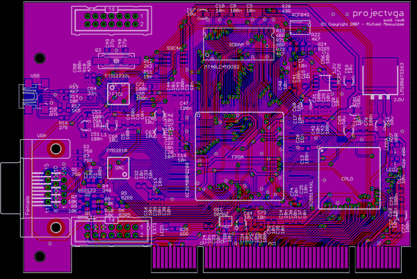
Finished Board art
Update 2008/01/02: Artist impression of board art addedPosted on 2007/12/23 - 14:55
Two things today, first, some info about the finished circuit board art and second, the promised remaining part about the Module design. The part of the module design will be added in the previous post. I clocked in about 75 hours in about 7 days to get the board art finished because due to all kinds of other events related to this project kept delaying it. So I sat down on the 7th of December, started drawing, and gave myself the deadline of finishing it before or on the 14th. It's unbelievable how much work you can get done if you simply ignore everything else in life and I made the deadline, sorta. Over the following weekend I did some final adjusting and finetuning because there were some details I didn't like, but overal I tossed version 1.1 of the board art online to collect some feedback. Last week I did get just that, so I further changed the board to have 8 mil clearance everywhere, fixed some font issues, and other relatively minor things. You can grab version 1.2 right here. The finished board looks like this:

Board art v1.2
Another reason for this push is that it'll take about two weeks before I'll actually get the manufactured circuit board and my university will be closed for almost two weeks during the holidays. So instead of being unable to continue for a month I figured it'd be wise to let these two overlap, and I ordered a couple of circuit boards two days ago. I haven't slept for two days either because I'm a little excited about it, so it'll be an interesting two weeks. In case you wonder about the details:
PCBcart order 21 Dec 2007
Material:		FR4
Layers:			2
Board Size (width):	122.99 mm
Board Size (height):	86.04 mm
Quantity:		3 pcs
Thickness:		1.6 mm
Surface Finish:		ENIG -Electroless Nickle/Immersion Gold - RoHS
Copper Weight:		35 um
Min. Tracing/Spacing:	0.20 mm
Min. Annular Ring:	0.30 mm
Smallest Holes:		0.40 mm
Holes Numbers:		300 - 600
Surface Mount:		1 side
Soldermask:		Both Sides
Peelable Soldermask:	None
Soldermask Color:	Black
Matt Color:		None
Silkscreen Legend:	1 side
Silkscreen Legend Color:White
Gold Fingers:		116
Cutouts/Slots:		4
Testing:		Yes
Routing:		Individual
Lead Time:		in 15 days

File:			Version 1.2
Unit price		€ 14,91
Quantity		3
Tooling cost		€ 42,06
Total			€ 86,78
Shipping cost		€ 16,38 (DHL)
Total			€ 103,16
That's actually very cheap for some prototype circuit boards. I figured that if I were to do this project, I might as well make it look nice, so I ordered them at PCBcart which has the possibility for 'hard gold' PCI fingers, manages the cutouts for me, can do a black finish of the soldermask and actually accepts Eagle files straight away - no worrying about gerber files. Pretty much everybody seems to have a good experience with them so I didn't mind the slightly higher cost. I prefer to have perfectly working boards than a few bucks cheaper, and not being sure if everything is correct. But even with all those features they're still far cheaper than any other shop I asked, so if the boards turn out to be correct other companies will have a hard time convincing me to use their services instead.
A final thing I want to note about the circuit board is that I won't be having any PCI brackets for it. After some searching I matched the holes and distance of the connectors with these but getting just a handful of those with the correct holes punched in them would cost me a small fortune. I might try to produce two or three of them by hand at my university, but if that won't work the prototype will simply have to do without a bracket.
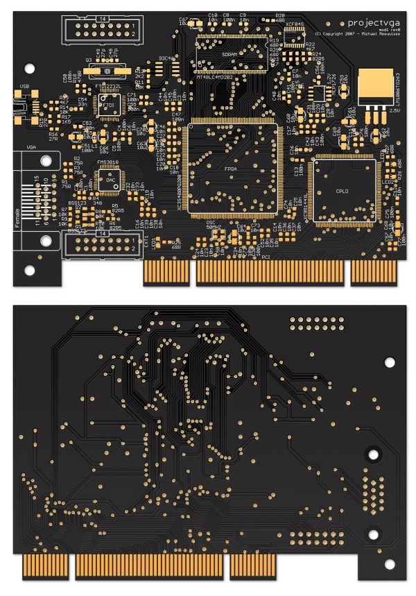
Update 2 Jan:
madwizard was kind enough
to do some photoshop magic and render a very nice version of the circuit board art, which hopefully gets close to
how the end result will look like. Enjoy:

Board art v1.2 - Photoshop rendering by madwizard
Happy holidays & Happy Newyear!
[: wacco :]


 You're on the Project VGA Page


